Manifest
manifest.json is the shared description of a sensor's geometry, wiring and optional shear groups. OpenTac-CAD includes it in every design ZIP. Lengths are expressed in millimetres, with Y increasing upward and the cable edge at the bottom. Downstream code should use the physical coordinates in pixels rather than infer geometry from scan indices.
from opentac import manifest
m = manifest.load("my_design.zip")      # or manifest.json, or a dict
m.xy, m.row, m.col, m.w, m.h            # taxel centres (mm), scan indices, taxel size
opentac manifest check FILE validates a manifest and says which readout
boards it fits.
Format versions
The field v is the version. Each version added fields and changed none, so
code written for version 3 reads all of them.
v |
Added |
|---|---|
| 3 | the base fields below |
| 4 | design: the recipe OpenTac-CAD uses to rebuild or edit the board |
| 5 | shear: which taxels share a shear bump |
| 6 | sim3d: where each taxel sits on the 3-D part it was unrolled from |
Manifest fields
| Field | Meaning |
|---|---|
pixels |
one [x, y, row, col] per taxel. Defines physical taxel positions and the ordering of values in each frame. |
w, h |
one taxel's width and height |
footprint |
the rest of the taxel copper: trace_w, gap, center_clear, edge_clear, via_drill, via_dia |
outline |
the shape the user drew |
edge_cuts |
the board as manufactured up to the connector: grown board and cable tail, closed across the connector's open edge (the Gerber Edge.Cuts adds the connector tab) |
r, c |
number of scan rows and columns |
m |
which taxels exist: r strings of c characters, 1 for a taxel |
rp, cp |
connector pad of each scan row and column |
px, py, ox, oy |
scan-order pitch and origin. Use pixels for physical geometry. |
shear |
bumps: bump centres. b: one entry per taxel, parallel to pixels, the taxel's bump index or -1 for none. |
design |
the CAD recipe (v4 on) |
sim3d |
3-D placement (v6, sensors designed on a mesh) |
_readme |
Human-readable notes; ignored by programs |
Scan indices follow connector-pad order, which can differ from spatial order. OpenTac-CAD reverses the lower half of the row indices to match routing on the right side. Consequently, expressions such as ox + col * px do not generally reconstruct taxel positions. Use the explicit coordinates in pixels.
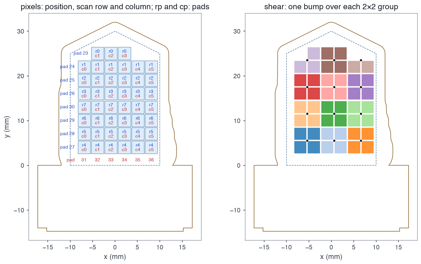
examples/manifests/finger_8x6_60pin.json: pixels with their scan rows (r) and columns (c), rp and cp (pads), and shear (right). Rows 4–7, the lower half, run upward. Dashed: outline; solid: edge_cuts.Validation constraints
manifest.load() validates the following constraints and reports the first violation:
mhasrrows ofccharacters of0/1.pixelslists exactly the taxelsmmarks, in the order of readingmrow by row.rphasrpads,cphascpads, and no pad is used twice.shear.b, if present, has one entry per taxel.- Positions are finite numbers;
wandhare positive.
A readout board also needs the taxels on one regular grid: every taxel position must be a whole number of pitches from the first one.
Configuration stored on the readout board
opentac setup uploads a compact scanning configuration: array dimensions, connector-line assignments, active-taxel mask, grid pitch and positions, and shear grouping. This uses 241 bytes for a 9 × 9 sensor and at most 2,336 bytes. The full pixels, outline, design and other fields remain on the host. The board stores the CRC-32 of the original manifest bytes as the sensor ID, and the host caches the file under that ID in ~/.opentac/manifests/.
Map connector pads to readout lines
A pad number in rp/cp is the pad on the sensor's cable tail. Which line of
the readout board it reaches belongs to the board, and is listed per board in
opentac/device/boards/*.json:
| Board | Pads | Pad p reaches |
|---|---|---|
| 60-pin | 1 to 60 | 62 - p: pads 1-30 are read by mux channels 29..0, pads 31-60 are driven by shift-register steps 31..2 |
| 30-pin | 1 to 30 | pads 1-15 are driven by shift-register steps 14..0, pads 16-30 are read by mux channels 14..0 |
Every taxel needs one driven line and one read line. The readout firmware accepts a skin with its rows on either side of the connector.